Friday, January 29, 2010

CNC Update!


Here is where most of my projects start, a pile of metal on the floor!  The steel yard I got it from even threw in the rust for free!

Here I am cutting some of the steel parts out on my amazing Black and Decker workmate 300 worbench!  I like it because not only is it a work bench but it also can clamp onto parts like these steel beams so I can cut them with a sawzall.

Here I am starting to center punch the holes to mount the linear rails for the "Y" axis to the 1/4" thick by three inch wide angle iron.  After the holes where center punched I drilled them out and tapped them for M5 bolts to hold the rails to the steel frame.

I thought about using bronze bushings to support the ends of the ballscrews because they are simple to mount but I ended up using some ball bearings to help things run smoother.  They started life as some Team Delta pillow blocks meant for fighting robots to roll around on, but after some work on the bandsaw they where cut down so that I got two smaller bearings from each pillow block.

Here I am drilling the mounting holes in the pillow blocks and the steel frame.  The small 1/2" shaft in the bearing passes through the steel as well and keeps everything lined up while I drill.

Here you can see the Y axis really coming together!  The parts are just laying there right now but you can see the mount for the stepper motor on the front 2" square tubing. You can also see the two linear rails mounted to the steel frame and the ballscrew running down the middle of it all that will move the Z axis left and right.

Here you can see one of those bearing blocks that I made in an earlier picture mounted and holding the ballscrew in place. I had to turn the end of the ballscrew down from 16mm to 1/2" to fit into this bearing and the LoveJoy coupler that connects the ballscrew to the motor.  Turning the hardned steel ballscrew on my Harbor Freight mini lathe was no small feat!  But I was able to do it.   More to come!

Saturday, January 23, 2010

CNC Router update!


I have been working on finalizing my cnc router's design for about a week now and I think I finally have it the way I want it.  Most of the router is going to be made from steel either 1/8" thick or 1/4" thick and the cutting table will be made from high density particle board.  This is my final CAD drawing of what the machine should look like.


Here is the machine with the cutting table removed  so you can see the inside.  Now its time to start cutting and welding some steel!

Saturday, January 16, 2010

CNC Router

Well it's a new month and I have a new project! I have always wanted a CNC router in my garage because you can build just about anything with one. For those unfamilier with what a CNC router does it's a machine that takes something you have drawn on the computer and cuts it out using a wood router that is moved left and right (which is called the X axis), forward and backwards (which is called the Y axis) and up and down (which is called the Z axis) all controlled by a computer. It can cut out 2D shapes as well as 3D shapes and the best part is it just plugs into your computer where a printer normally would.


This is a CAD drawing I made of what my machine is going to look like.  One of the most important parts of a CNC router is the linear bearing and motion systems. I am using 16 and 20 mm round linear rails and bearings to support the machine and stepper motors driving 16mm Ballscrews for movement.  The spindle motor will be a 2 HP Dewalt router that will have a remote speed controller.


Here is where it all started, a 2' square plate of 1/4" 6061 aluminum.  My Z axis is going to be made out of aluminum and the rest of the machine will be steel welded together.


Here I started to cut the parts out, I needed this small square and then a larger rectangle that will make the frame for the Z axis which will move the router up and down.


Here is everything after I drilled some holes and mounted the linear bearings, ballscrew and stepper motor.  I used a Lovejoy coupler to attach the 1/4" motor shaft to the ballscrew.


Here it is from another angle, the Dewalt router will mount to the smaller top plate.  There is 6" that the router will be able to move up and down.  Up next is to get a bunch of steel and build the rest of the frame out of it!


Here is a random video of a CNC router in action and below it are some random pictures I stole from the internet on things you can build with one.


Friday, January 8, 2010

December - Finished!


December was crunch month!  I ended up working my days off at work so that I could take some days off to go to Combots and compete with the robot, this made a LOT less time avaliable to actually finish the robot but I managed to get it done.  After I had all the brackets to mount the components welded in I stripped all the parts back out of the frame and then I ground and sanded the welds down to make them look nice.  I hung the frame and the aluminum wheel pods from my garage rafters and hit them with my signature Red and Black paint job.


Here is the frame ready to have all the components put back in.  Although I used steel to build the frame it ended up only weighing 12 pounds as it sits in this picture and it is VERY solid.


Here I have the drive pods bolted back on with the Dewalt motors mounted.  The armor panels are not square and they twist to match the frame when bolted on.  I made some patterns out of cardboard and then traced then onto the 3/32" thick lexan that makes up the bulk of the armor (I know its really thin, but after several competitions fighting with LW bots I have never had it be a problem)


Here is some of that thin lexan that will make up the back armor.  I needed to bend it to match the back end of the bot so I clamped it to my workbench like this picture shows and used a rubber mallet to make the bend.


Here the major rats nest of wires is starting to take shape.  Every one calls me old school but I use a Vantec RDFR36E to control Hot Stuff. It is a little heavy but handles the four Dewalt motors great and has proved itself bullet proof through two comps now.


This is how you know the robot your building is going to be very animated, no empty rx channels!  Although one of them is just the rx battery monitor the robot uses FIVE channels to control everything it does.  Yes it is a handfull to drive!


Here I am trying to shave some weight off the side armor by removing half the material.  In the end I ended up being almost two pounds over weight at the competition and I had to remove most of the side armor, part of the top armor and a bunch of redundant  hardware was removed or changed out to aluminum to get Hot Stuff to 60 pounds.


The all steel arm in last months progress report was much to heavy so I made a new arm that was mostly aluminum.  Here are the two main spars fresh off the bandsaw.  I drilled a bunch of holes in them next to remove weight.


In this picture you can see I made a new lifting fork from steel that bolts to the end of the aluminum arm.  I tried square tubing this time to see if that would scoop other robots better than the round tubing I used last time (It was pretty much the same) I ended up reusing the grabbing arm from Kassinator on this robot since I was running out of time to get the bot done.  You can also see the 1/4" thick lexan I used for front armor in this picture as well as the two 5/8" diamater spikes I had on both the front corners to use as outriggers.  These where made from 6-4 Titanium and help up great!


Here is a close up of where the fire comes from in Hot Stuff.  I used a nozzle meant for an air compresser blow gun for the flame nozzle.  Wires where run from the BBQ sparker to the front of the arm and you can see the two little copper wires in front of the nozze where the sparking happens.  It took a LOT of fine tuning to get the spark to actually ignite the gas.


In this picture you can see the 9 oz paintball tank I use to power the lifting and grabbing arm.  It may seem kind of small but I have never ran out of gas in a match before.  I use a palmer Regulator to bring the tank pressure down to 150 psi and it works great at keeping liquid Co2 from getting past the regulator (which is bad news as your low pressure side is all of the sudden hit with ~900 PSI of pressure)  There is an emergancy blow off valve on the low pressure side that is set for 165 PSI and that has saved my bacon the few times liquid Co2 has made it past the regulator.


Here is a shot of the electronics on the finished robot.  For an on and off switch I used a removable like again made from Anderson Power Poles, worked great and weighs almost nothing.  You can see everything is really packed in there!


Photo Courtesy of Team Toad.

Here is the ultimate battle of hot and cold; Hot Stuff vs Frosty the snow bot!  Combots was a blast and despite needing a few hours of repair work after each match Hot Stuff came out undefeated!  Although the Finals was an especially close call!  I think people enjoyed watching the robot fight and I'm planning on bringing a mostly unchanged Hot Stuff to Robogames this spring.

Video of Fianls: http://www.youtube.com/watch?v=95hVgSNHKs4


Tuesday, December 1, 2009

November Progress


Over the last few months I have been working on getting the drive pods for the robot done.  This month I have been working on joining those two drive pods with a welded steel frame that will make up a bulk of the robot in both size and shape.  I prefer to build robots that have lots of angles instead of flat and box shaped parts both because I feel they look a little better and angles deflect hits well.
The above picture shows the first two pieces of steel cut and laid out on one of the drive pods.


To get the drive motors to sit flat agaist the drive pods I had to use my milling machine to cut the mounts down a little on the edges to let them clear the 1/8" thick steel frame.


Here I am taping a hole in the drive pod to bolt the steel frame to it, and two pieces already bolted down.


I usually work on my robot early in the morning so having a fridge stocked with Mt Dew is a must!  I spaced all those drinks out over a few days, I promise!


I already know this robot is going to be to heavy since the last version was 60.0 pounds on the Robogames scale, so this time around I am taking steps early on to try to bring the weight down a little since I am going with heavier drive motors and the addition of a flame thrower.  Here I am drilling some holes in a steel frame piece.


Tho one with the holes is weighs about half as much as the solid one and probably less than half as strong, but its all a weight game.


The aluminum drive pods are the next thing to loose some meat.  Here I have marked with a marker where I want to remove some material.


I used my milling machine to cut out the rectangles in the aluminum, it takes about four passes to cut through the 1/4" 6061 taking 1/8" off at a time.


I also drilled some holes in the bottom of the drive pod, it's looking like swiss cheese!


Here are both drive pods after they have been lightened and the first parts of the steel frame bolted on.  since you can't weld steel to aluminum I used some 1/4-20 button head cap screws to hold the two disimilar metals together.


Next up on the to do list was to shorten the drive shafts to thier final length and cut the groves in them for the snap rings.


Here they are shortened up.  I used a sawsall to cut them off and then I turned the ends on my lathe.  While they where in the lathe I cut another groove for a snap ring on the end.


Here is a picture of both sides of the drive pods showing the snap rings in place.  This is the first time I have used these and so far I am happy with them.  They are much lighter, cheaper and smaller than a shaft collar.


To join the two drive pods together I started out cutting some 1/8" thick 3/4" wide steel bar into strips.


After spending what felt like forever squaring things up I welded the bars into place, checking to make sure things stayed square several times.


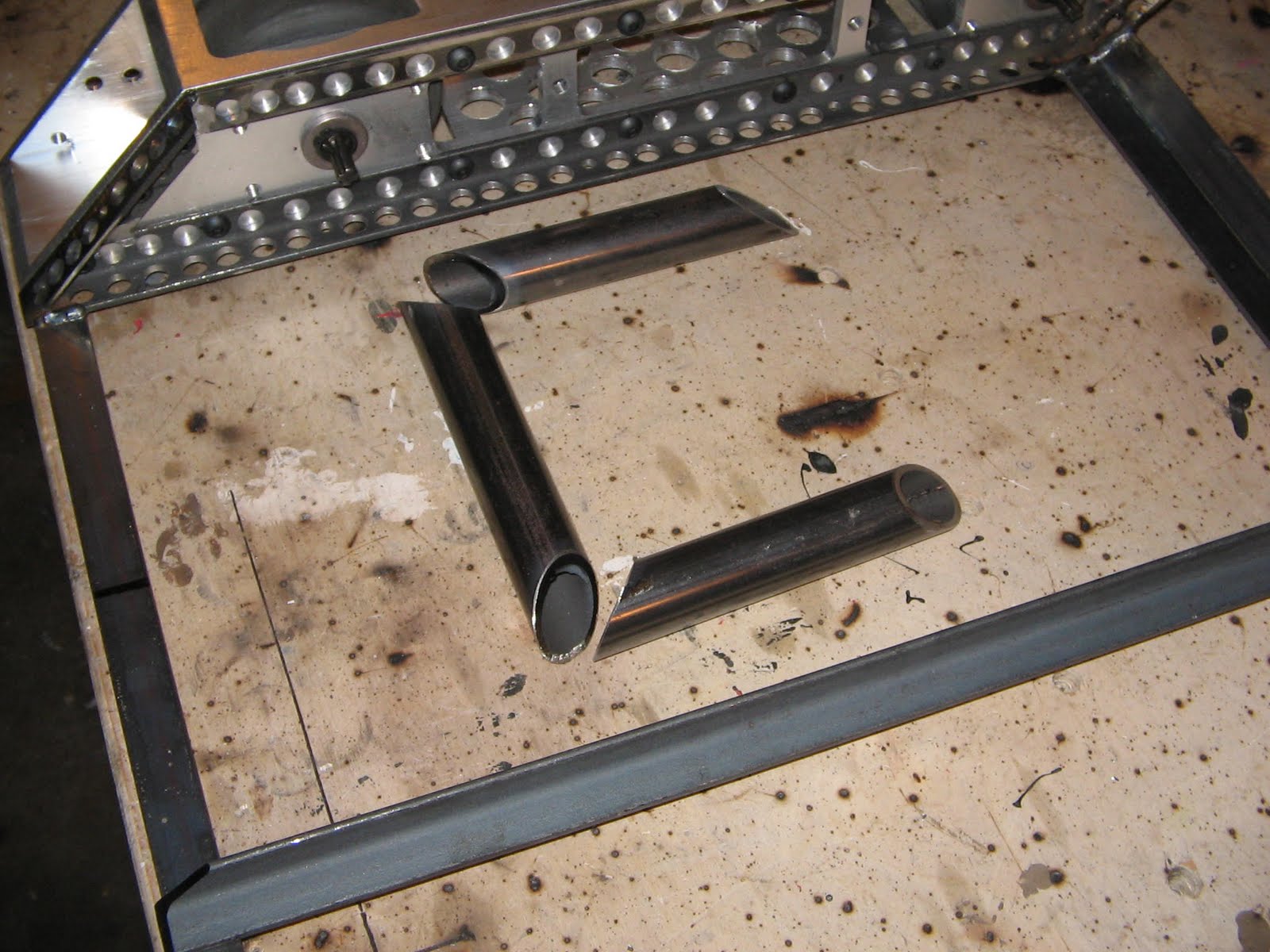
This picture shows the tubing I am using for the lifting forks this time around, its pretty heavy duty stuff.


Here is the lifting forkes welded up so I can use them for layout purposes.  In the background you can see me starting to lay out internal spars in the frame.


Several of the frame members had to be milled to allow clearance for the pieces they sit on, here I am taking the lip off this piece of angle iron.


And here is that same piece showing why I needed to do the previous step, it sits nice and flush now, ready to be welded together.


Here are the parts to the bracket I made to hold down the air cylinder, I used 3/16" steel for these parts.


Here they are welded in place.  Notice the frame rails only have holes drilled in them on one side, I left the side alone that will see lots of force from the lifting arm.  These two frame rails bending would be BAD news.


Here is the air cylinder mounted, its looking like a Bot!


Its kind of hard to see in these pictures, but there is now two vertical supports welded towards the back of the robot, these are what the lifting arm will mount to and pivot on.


Here I am about half way done with the arm, now I just need to join the upper and lower pieces.


All done!  This part of the robot bent at the last robo games so I tried out a different design this time.


Here is the back end of the bot starting to take shape.  I am using lots of 1/8" x 3/4" strap to build this frame. 


Here I am building the front of the bot. There are lots of tricky angles this time around but I think it will look good when it is done.


Ok, I obviously slacked off taking pictures for a little while, with the event about two weeks away I have been picking up the pace a little. This picture shows the frame almost done and most of the components mounted.


I had to create several brackets to hold all the internal parts in, and I reused several mounts from the last robot as well since some of tha parts are the same.


Everything is smashed in there!  The butane tank ended up closer to the Dewalt motor then I would like (the picture makes it hard to tell but there is just under a 1/4" between them.)  I'm thinking of putting a chunk of Silicone rubber inbetween them to keep the heat from the motor away from the tank.

Thats all for November!  I have about two weeks to finish the Bot, its going to be a close one!