Tuesday, December 1, 2009

November Progress


Over the last few months I have been working on getting the drive pods for the robot done.  This month I have been working on joining those two drive pods with a welded steel frame that will make up a bulk of the robot in both size and shape.  I prefer to build robots that have lots of angles instead of flat and box shaped parts both because I feel they look a little better and angles deflect hits well.
The above picture shows the first two pieces of steel cut and laid out on one of the drive pods.


To get the drive motors to sit flat agaist the drive pods I had to use my milling machine to cut the mounts down a little on the edges to let them clear the 1/8" thick steel frame.


Here I am taping a hole in the drive pod to bolt the steel frame to it, and two pieces already bolted down.


I usually work on my robot early in the morning so having a fridge stocked with Mt Dew is a must!  I spaced all those drinks out over a few days, I promise!


I already know this robot is going to be to heavy since the last version was 60.0 pounds on the Robogames scale, so this time around I am taking steps early on to try to bring the weight down a little since I am going with heavier drive motors and the addition of a flame thrower.  Here I am drilling some holes in a steel frame piece.


Tho one with the holes is weighs about half as much as the solid one and probably less than half as strong, but its all a weight game.


The aluminum drive pods are the next thing to loose some meat.  Here I have marked with a marker where I want to remove some material.


I used my milling machine to cut out the rectangles in the aluminum, it takes about four passes to cut through the 1/4" 6061 taking 1/8" off at a time.


I also drilled some holes in the bottom of the drive pod, it's looking like swiss cheese!


Here are both drive pods after they have been lightened and the first parts of the steel frame bolted on.  since you can't weld steel to aluminum I used some 1/4-20 button head cap screws to hold the two disimilar metals together.


Next up on the to do list was to shorten the drive shafts to thier final length and cut the groves in them for the snap rings.


Here they are shortened up.  I used a sawsall to cut them off and then I turned the ends on my lathe.  While they where in the lathe I cut another groove for a snap ring on the end.


Here is a picture of both sides of the drive pods showing the snap rings in place.  This is the first time I have used these and so far I am happy with them.  They are much lighter, cheaper and smaller than a shaft collar.


To join the two drive pods together I started out cutting some 1/8" thick 3/4" wide steel bar into strips.


After spending what felt like forever squaring things up I welded the bars into place, checking to make sure things stayed square several times.


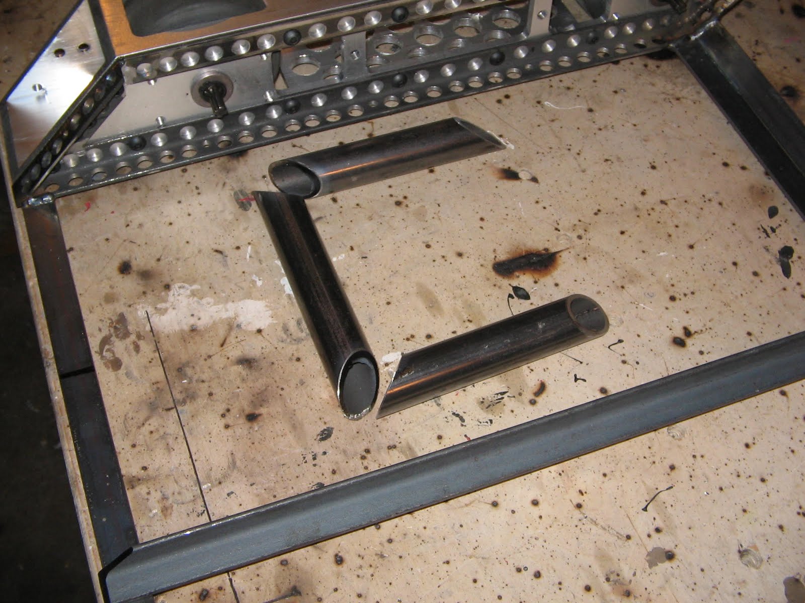
This picture shows the tubing I am using for the lifting forks this time around, its pretty heavy duty stuff.


Here is the lifting forkes welded up so I can use them for layout purposes.  In the background you can see me starting to lay out internal spars in the frame.


Several of the frame members had to be milled to allow clearance for the pieces they sit on, here I am taking the lip off this piece of angle iron.


And here is that same piece showing why I needed to do the previous step, it sits nice and flush now, ready to be welded together.


Here are the parts to the bracket I made to hold down the air cylinder, I used 3/16" steel for these parts.


Here they are welded in place.  Notice the frame rails only have holes drilled in them on one side, I left the side alone that will see lots of force from the lifting arm.  These two frame rails bending would be BAD news.


Here is the air cylinder mounted, its looking like a Bot!


Its kind of hard to see in these pictures, but there is now two vertical supports welded towards the back of the robot, these are what the lifting arm will mount to and pivot on.


Here I am about half way done with the arm, now I just need to join the upper and lower pieces.


All done!  This part of the robot bent at the last robo games so I tried out a different design this time.


Here is the back end of the bot starting to take shape.  I am using lots of 1/8" x 3/4" strap to build this frame. 


Here I am building the front of the bot. There are lots of tricky angles this time around but I think it will look good when it is done.


Ok, I obviously slacked off taking pictures for a little while, with the event about two weeks away I have been picking up the pace a little. This picture shows the frame almost done and most of the components mounted.


I had to create several brackets to hold all the internal parts in, and I reused several mounts from the last robot as well since some of tha parts are the same.


Everything is smashed in there!  The butane tank ended up closer to the Dewalt motor then I would like (the picture makes it hard to tell but there is just under a 1/4" between them.)  I'm thinking of putting a chunk of Silicone rubber inbetween them to keep the heat from the motor away from the tank.

Thats all for November!  I have about two weeks to finish the Bot, its going to be a close one!

Friday, October 30, 2009

October Progress


I didn't get a rolling robot by the end of October like I had hoped, but I did get a lot done! First off the bot is getting a name change.  My wife suggested that since the robot was going to have a flame thrower that I should name it "Hot Stuff". I like it so the name sticks! Last month I left off with getting the bushings pressed into the wheel pods, this month I focused more on finishing the pods up.  First thing I needed to do was make it so the drive shafts would not slide side ways in the bushings.  A great way to do this if you have a lathe that is really light weight is to use snap rings like the one shown in the picture above

To use a snap ring you need a special cutter that will cut a grove in your drive axle that the ring can "snap" into, I used some 1/4" lathe stock to make my cutter.

A little work on the sander to get the cutter the right shape and I was ready to go!

The cutter is now just slightly wider than the snap ring and is ready to cut the grove.

Here it is in action.

Here is the snap ring installed.  This slides right up against the bushingand keeps the axle from sliding sideways.  I will do this to the other side as well the the axle will stay put.

I needed to make an adapter to go inbetween the Dewalt motor and the drive pods.  I started by cutting some 1/2" lexan into a strip on the Bandsaw.

Then I cut the strip into smaller rectangles.


I marked the placed where the mounting holes needed to go and then center punched them to keep the drill bit from wondering.

Here is the completed motor mount ready to get the holes counter sunk.

Next I needed to drill matching holes in the wheel pods.  I'm using a center punch here to to keep the holes where I want them.

Here I am drilling the holes.

I don't like using to many nuts on my robots to make everything easy to put together so here I am using a 1/4-20 tap to thread the holes I drilled so the bolts thread right into the 1/4" aluminum.

Here is a completed motor mount bolted to the Dewalt motor.  those four holes in the lexan are used to bolt the whole thing to the drive pod.  The dewalt splined input just slips over the splined shaft the the snap rings keep everything in place.

The tires I am using are a little wider than I would like with all that extra plastic on the hubs.

Here I am turning off the extra width I don't want from the tire.

All done, nice and smooth!

Here is a shot of my bushing set up.  I used bronze thrust bushings to go inbetween the tire and the

Close up.

After I got all the motor mounts made I bolted them on and checked to see if I can cram everything in that I need to.  The last version of the bot was pretty cramped and this time around I am trying to cram in a 3.5 oz propane tank too.

With the upgraded drive motors I worried my duct tape battery packs I used last time would not let my 2.4 ah sub c battery packs breath enough to stay cool.  I took a cue from the intercooled Battle Packs and decided to make cell spacers that would double as the battery pack mount.

Here I am sanding all the lexan blanks to be the same size as each other that will make up my intercooled pack cases.

I used a 7/8" flat drill bit to make the pockets for the cells since my mill is not big enough to hold a milling cutter that size.  I had to grind the little points off the side of the bit as well as grind down the center point to make it just the right size to make the pockets.

Here I am using the bit to cut out the pockets for the cells.

One down, three to go!

After I had all the pockets in I needed to cut slots between them for the wires to pass from one cell to another.

The casses are done!

I laid the cells in their places and then soldered deans wire between them to form the packs.

these are each 16.8V 2.4ah.  This was the maximum number of cells that I could mount inside the wheel pods and still have them fit between the tires.  I will have two more 6 cell packs somewhere else in the bot to bring the total voltage up to 24.

These battery packs will slip into the wheel pods before the tires go in.  I needed a way to get the wires from the batteries into the bot, so I milled slots for them to pass through.


Here is the pack mounted inside the drive pod.

Inside shot of the same thing.

Since Hot stuff is a robot designed to pick up other robots that are equal in weight the robot relies on outriggers from the front to keep from face planting.  The ones used on Kassinator where kind of last minute additions and didn't hold up to combat well.  they where just some 1/4" lexan I cut to shape on the bandsaw and bolted onto the sides.

The new outriggers are going to be some 5/8" diameter round 6-4 Titanium spikes.  I needed a way to mount the titanium spikes to the robot so I started with a 7/8" diameter chunk of steel.

I bored a 5/8" diameter hole for the spike to slide into.

Here are the two spike mounts before I weld tabs on them to bolt them into the frame.

I used some 3/16" flat stock to make the tabs, cut out with my sawz all.

Here are all the mounting tabs cut out.

I ground a little angle on one of the tabs to get it to clear the frame, then clamped all the pieces into a scrap chunk of angle to weld them together.

Getting there!

I drilled and tapped holes into the round part that will be used to clamp the titanium spike in place.

Then drilled and tapped the tabs to mount into the frame.

Here is the chunk of Titanium rod that will make up the spikes.

Here is the mount bolted in.

Same thing from the outside.

The last robot only had the 1/4" 6061 aluminum drive pid for side armor.  This worked ok but I was horrified to think what would have happened had I fought a horizontal spinner like Rut Factor!  So this year in addition to the 1/4" aluminum I will have half an inch of lexan over the sides to bring up the armor thickness to 3/4". I used the bandsaw to cut out the armor pieces.

Perfect fit!

I used a 1" flat drill bit to cut some pockets for the drive bishings to clear.

With the pocket the lexan can sit flat against the aluminum.

I used a router to round off the top and bottom edges to make it look a little nicer.

Here I am getting ready to drill the holes to mount the armor to the pods.

Holes drilled and ready for bolts!  Thats all for this month.  I am working towards getting the bot done for Combots in December, so if its not rolling by the end of next month I am going to be in trouble!